
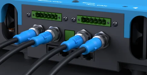
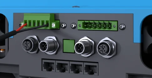
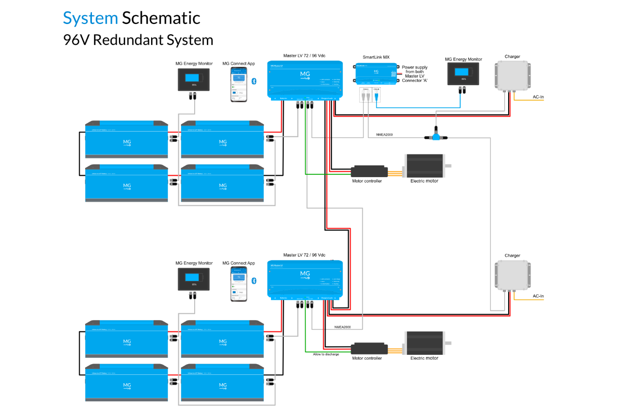
The Master LV comes with two integrated I/O ports. To sum up some of the functions:
 Allow to charge Allow to discharge 12 Vdc – 1 A Auxiliary output Programmable Relay. To start a generator, or heater. Remote Start-Stop button
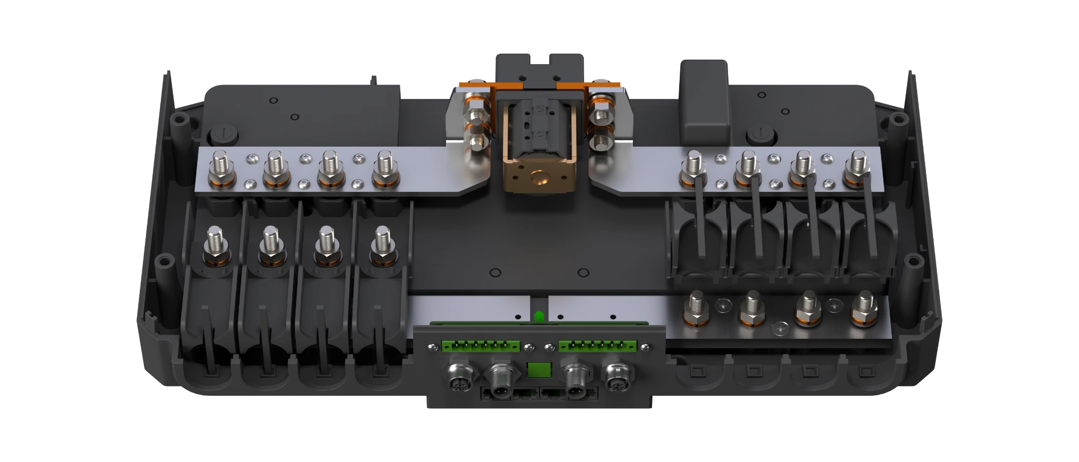
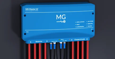
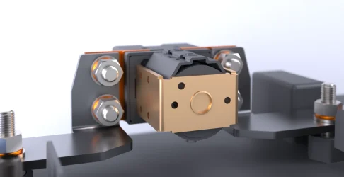
Safety Contactor
In order to guarantee a safe operation of the system, a safety contactor is integrated. It can disconnect the batteries from the chargers and loads. This is a second layer of protection. The built-in pre-charge circuit prevents the safety contactor from sparks and welding.
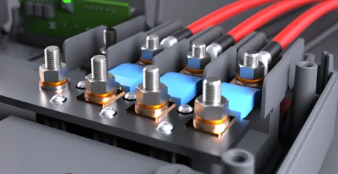
1 of 8Fuse holders
The fuse holders in the DC distribution system ensure maximum safety of your energy storage system. They protect the cables and components against excessive currents and short-circuits. Up to eight MEGA-fuses can be placed inside the MG Master LV.
2 of 8Shunt
The shunt measures the current from and to the batteries. This gives insight into the actual current when charging or discharging the connected batteries. Additionally, the shunt keeps track of the State-Of-Charge and protects the battery bank when there is an excessive charging current.
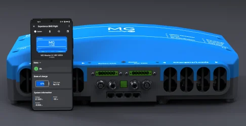
3 of 8Bluetooth
The bluetooth function makes it possible to monitor and control your battery system with your mobile phone or tablet. Use the MG Connect app to gain insight into the status of your MG battery system.
4 of 8Pre-charge circuit
Pre-charging increases the lifespan of electronic components and the reliability of the system. During the power-up procedure, the inrush current is limited to protect system components from damage.
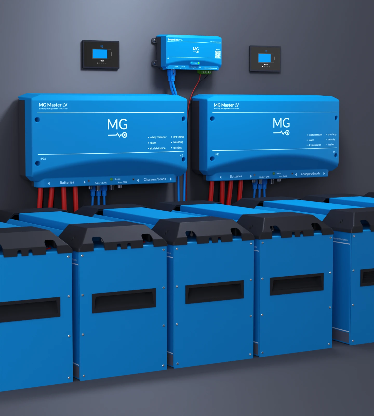
5 of 8DC Distribution
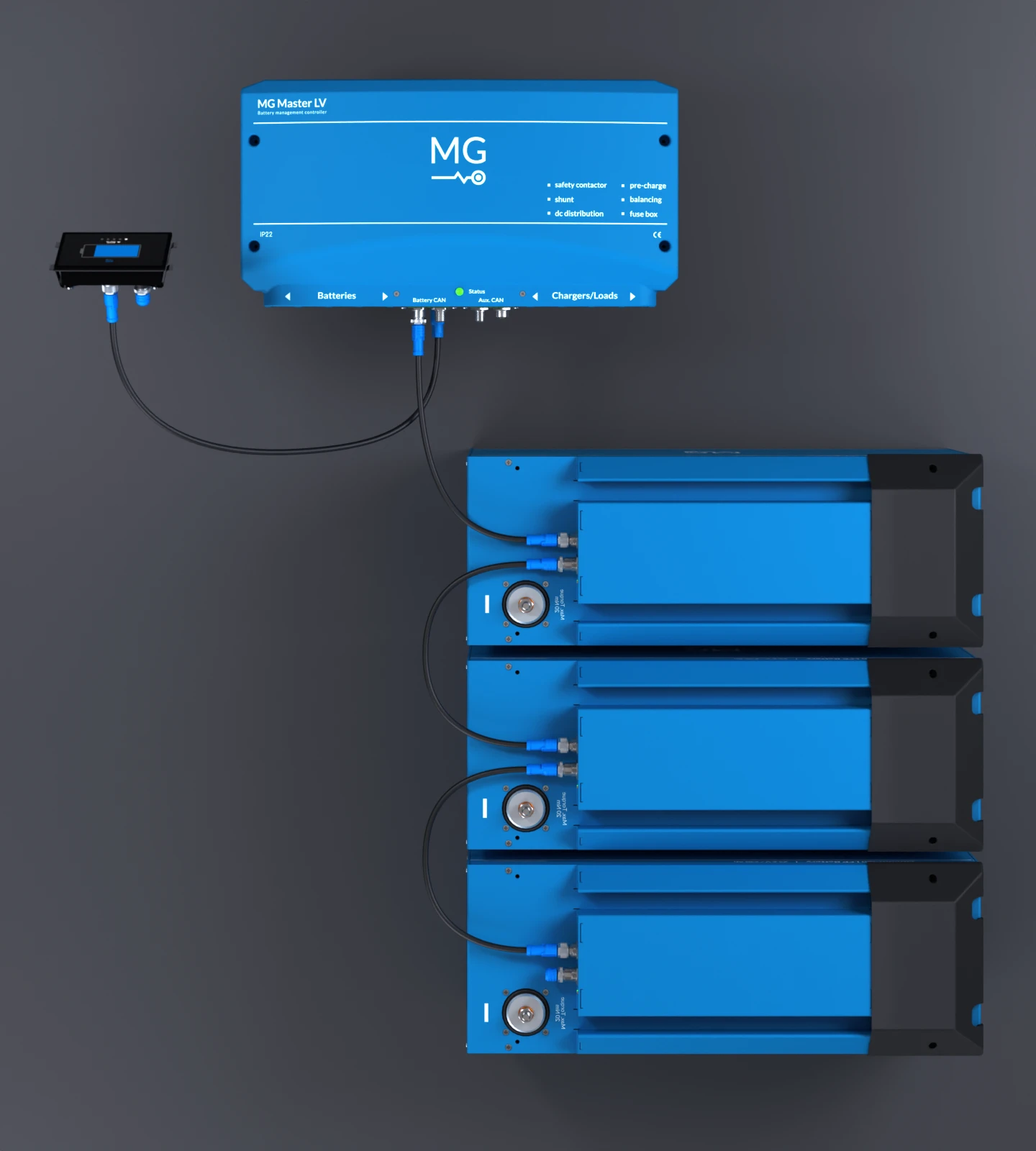
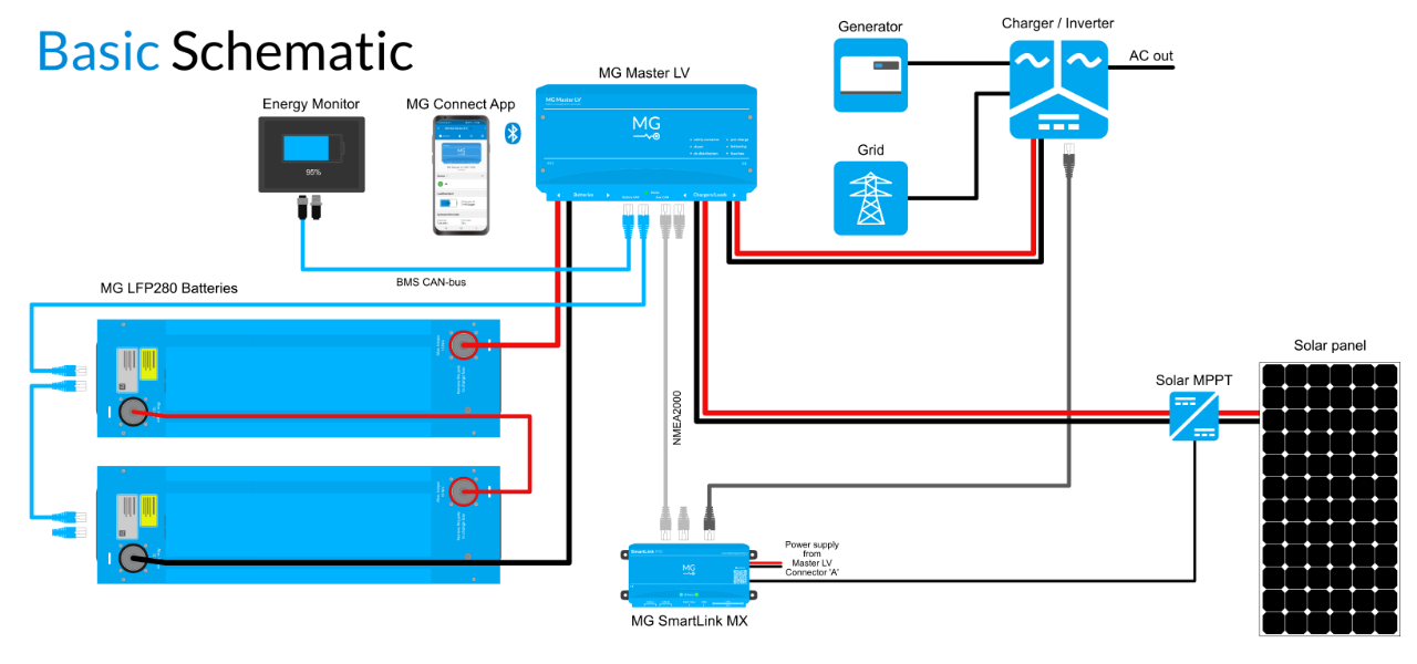
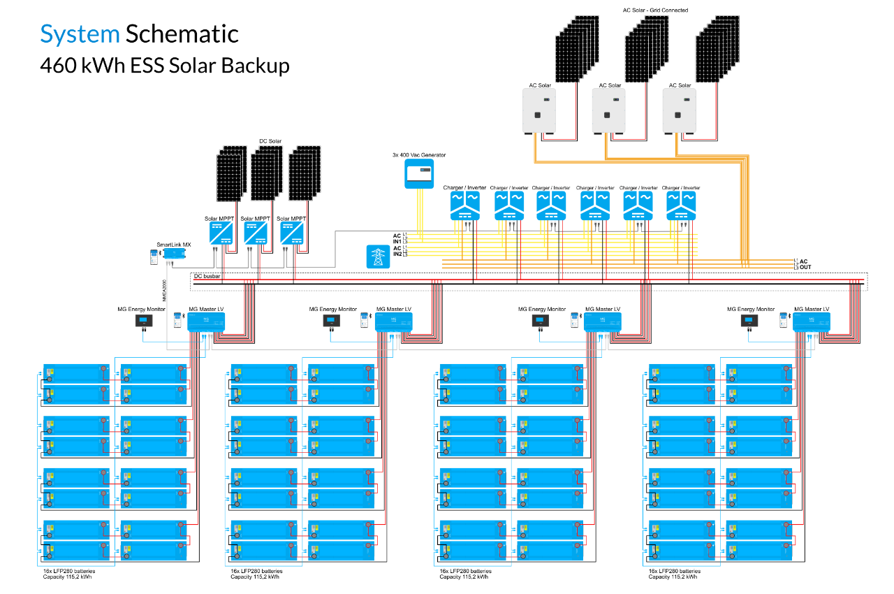
The busbar acts as a DC distribution system. Connect the MG batteries on the left side of the Master LV. Connect your DC chargers and DC loads directly on the right side of this internal DC busbar. Examples of loads are an inverter, electric drive or electric pump.
6 of 8Start Button
Easily press the button 3 seconds to turn the Master LV ON and OFF. This can either be done on the device itself or with a remote connected button.
7 of 8Status LED
The Status LED indicates the state of the system.
8 of 8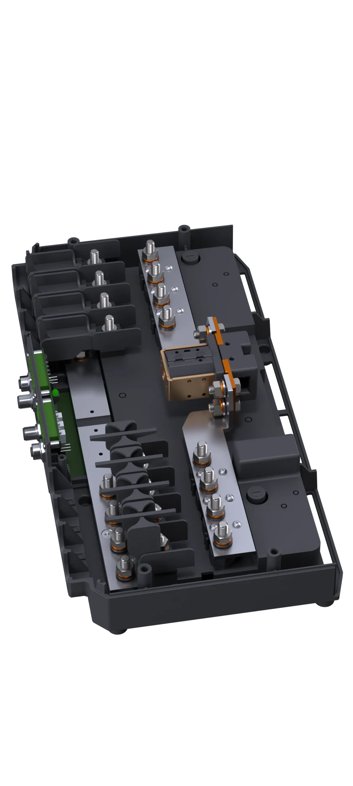
Safety Contactor
In order to guarantee a safe operation of the system, a safety contactor is integrated which can disconnect the batteries from the chargers and loads. This is a second layer of protection. The built-in pre-charge circuit prevents the safety contactor from sparks and welding.
1 of 8Fuse holders
The fuse holders in the DC distribution system ensure maximum safety of your energy storage system. They protect the cables and components against excessive currents and short-circuits. Up to eight MEGA-fuses can be placed inside the MG Master LV.
2 of 8Shunt
The shunt measures the current from and to the batteries. This gives insight into the actual current when charging or discharging the connected batteries. Additionally, the shunt keeps track of the State-Of-Charge and protects the battery bank when there is an excessive charging current.
3 of 8Bluetooth
The bluetooth function makes it possible to monitor and control your battery system with your mobile phone or tablet. Use the MG Connect app to gain insight into the status of your MG battery system.
4 of 8Pre-charge circuit
Pre-charging increases the lifespan of electronic components and the reliability of the system. During the power-up procedure, the inrush current is limited to protect system components from damage.
5 of 8DC Distribution
The busbar system inside the MG Master LV acts as a DC distribution system. Connect the MG batteries on the left side of the Master LV. Connect your DC chargers and DC loads directly on the right side of this internal DC busbar. Examples of loads are an inverter, electric drive or electric pump.
6 of 8Start Button
Easily press the button 3 seconds to turn the Master LV ON and OFF. This can either be done on the device itself or with a remote connected button.
7 of 8Status LED
The Status LED indicates the state of the system.
8 of 8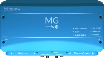


Battery Management System
Master LV
Master HV
Monitoring & Control
Energy Monitor
Connect App
Energy Portal
Battery Combiner
SmartLink MX
MG Batteries
4 of 4