 Integrated pre-charge circuit Safety contactors in positive and negative power paths High Voltage Interlock Loop (HVIL) Internal event logging
CAN-Bus communication Tracking State-Of-Health and State-Of-Charge Monitoring of all battery parameters
Integrated pre-charge circuit Safety contactors in positive and negative power paths High Voltage Interlock Loop (HVIL) Internal event logging
CAN-Bus communication Tracking State-Of-Health and State-Of-Charge Monitoring of all battery parameters
Integrated pre-charge circuit Safety contactors in positive and negative power paths High Voltage Interlock Loop (HVIL) Internal event logging CAN-Bus communication Tracking State-Of-Health and State-Of-Charge Monitoring of all battery parameters
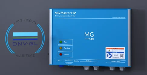
This high voltage BMS comes with the following type approvals as a standard:
DNV-GL Lloyds ES-Trin 62619 & 62620
This high voltage BMS comes with the following type approvals as a standard:
DNV-GL Lloyds ES-Trin 62619 & 62620
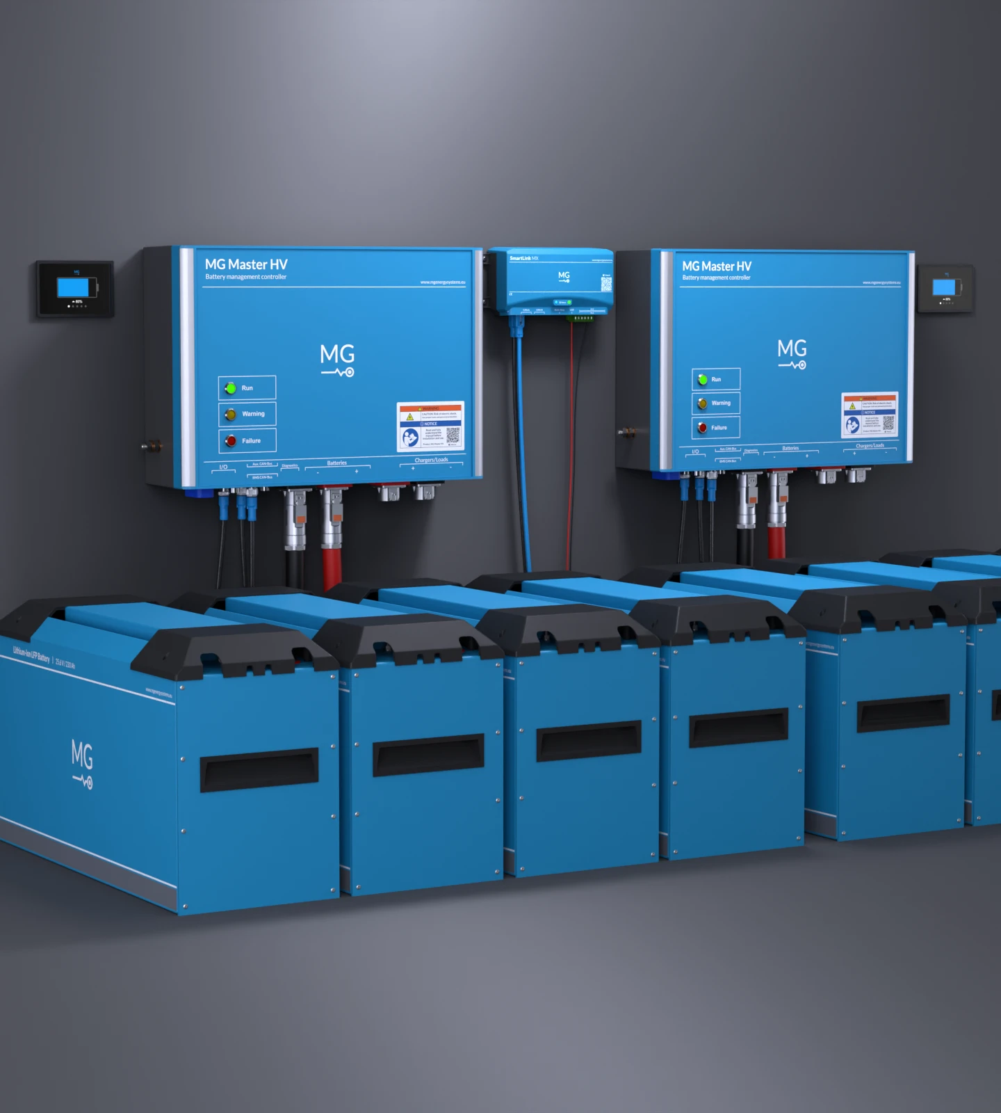
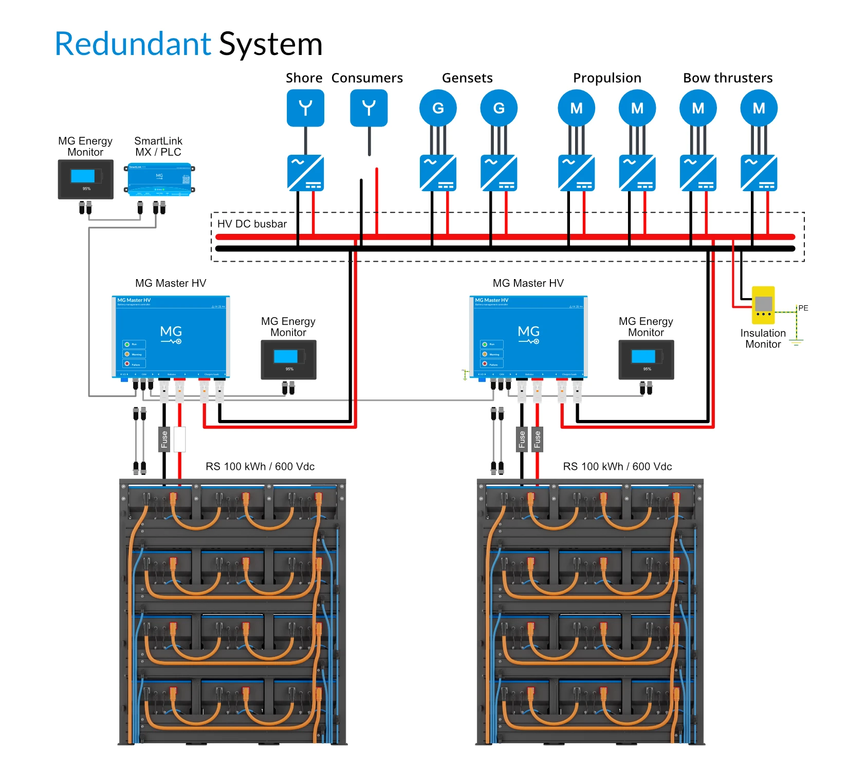
The integrated EMS sends and receives information to and from a PMS*, for monitoring and control of your energy storage system. The available protocols are NMEA2000 and J1939 (compatible). This includes the following functions:
 PLC CAN-Bus control Start/Stop/Reset BMS limits for chargers/inverters available Heartbeat mechanism protocol

The integrated EMS sends and receives information to and from a PMS*, for monitoring and control of your energy storage system. The available protocols are NMEA2000 and J1939 (compatible). This includes the following functions:
PLC CAN-Bus control Start/Stop/Reset BMS limits for chargers/inverters available Heartbeat mechanism protocol


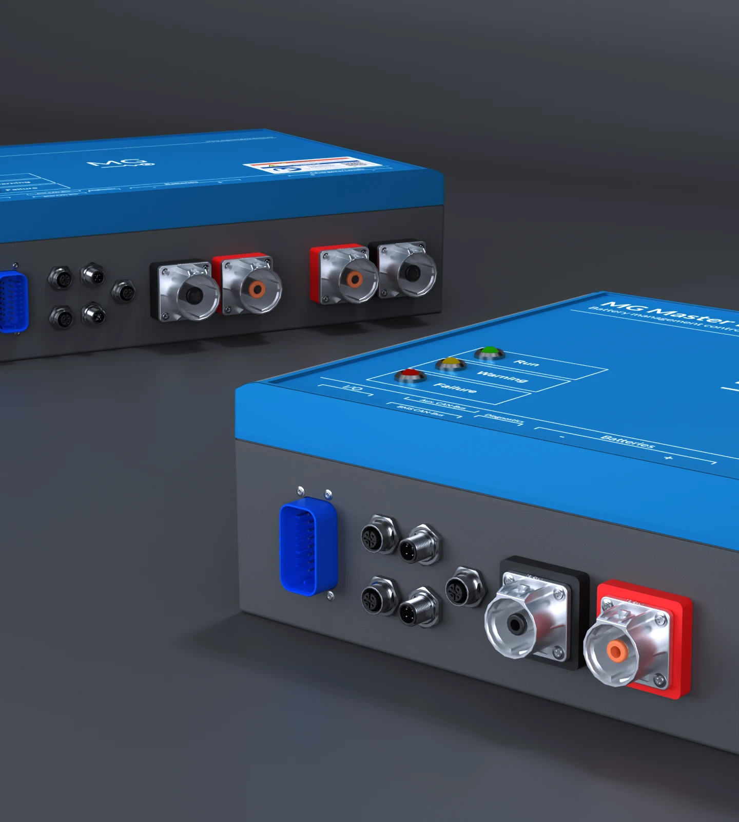
Pre-charge circuit
Pre-charging increases the lifespan of electronic components and the reliability of the system.
During the power-up procedure, the inrush current is limited to protect system components from damage.
Current Sensor
The current sensor measures the current from and to the batteries. This gives insight into the actual current when charging or discharging the connected batteries. Additionally, the current sensor keeps track of the State-Of-Charge and protects the battery bank when there is an excessive charging current.
2 of 9Safety Contactor
In order to guarantee a safe operation of the system, a safety contactor is integrated which can disconnect the batteries from the chargers and loads. This is a second layer of protection.
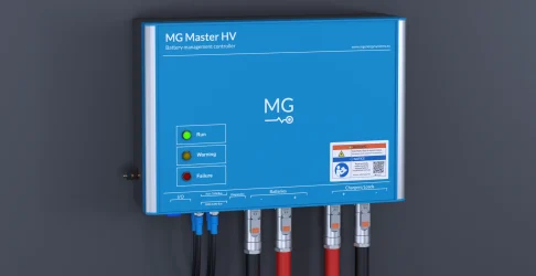
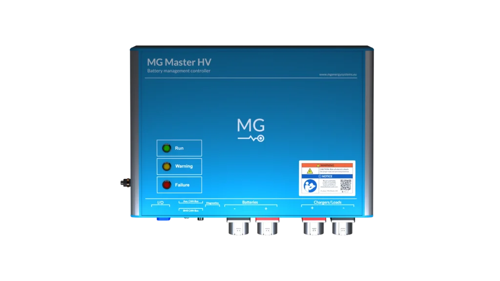
3 of 9Status LED
The Status LEDs indicate the state of the system.
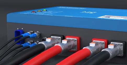
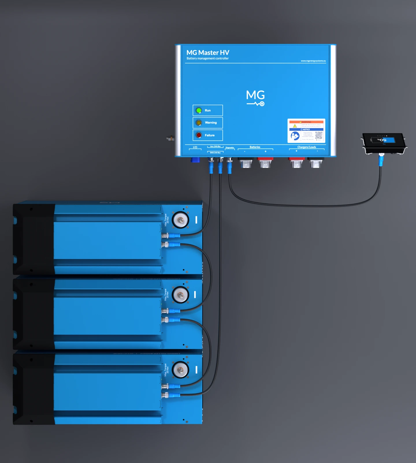
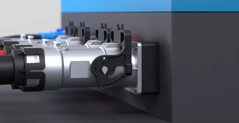
4 of 9Power Connectors
There are two models of the MG Master HV, the 300 A and 500 A. The only difference between the two models are the power connectors. This means that they differ in the maximum allowable current.
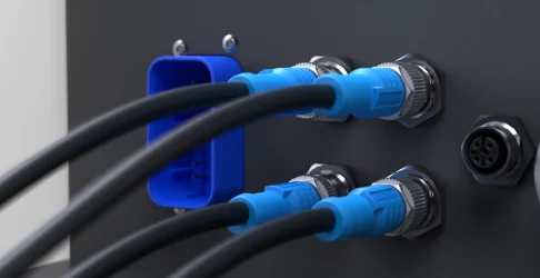
5 of 9Diagnostic port
6 of 9BMS CAN
7 of 9Aux. CAN
8 of 9I/O connector
9 of 9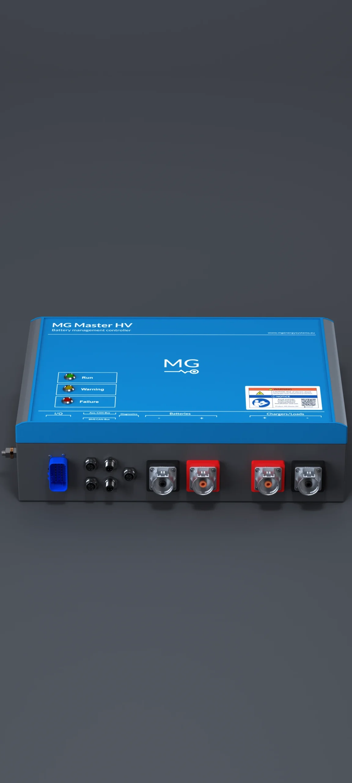
Pre-charge circuit
Pre-charging increases the lifespan of electronic components and the reliability of the system.
During the power-up procedure, the inrush current is limited to protect system components from damage.
Current Sensor
The current sensor measures the current from and to the batteries. This gives insight into the actual current when charging or discharging the connected batteries. Additionally, the current sensor keeps track of the State-Of-Charge and protects the battery bank when there is an excessive charging current.
2 of 9Safety Contactor
In order to guarantee a safe operation of the system, a safety contactor is integrated which can disconnect the batteries from the chargers and loads. This is a second layer of protection.
3 of 9Status LED
The Status LED’s indicate the state of the system.
4 of 9Power Connectors
There are two models of the MG Master HV, the 300 A and 500 A. The only difference between the two models are the power connectors. This means that they differ in the maximum allowable current.
5 of 9Diagnostic port
6 of 9BMS CAN
7 of 9Aux. CAN
8 of 9I/O connector
9 of 9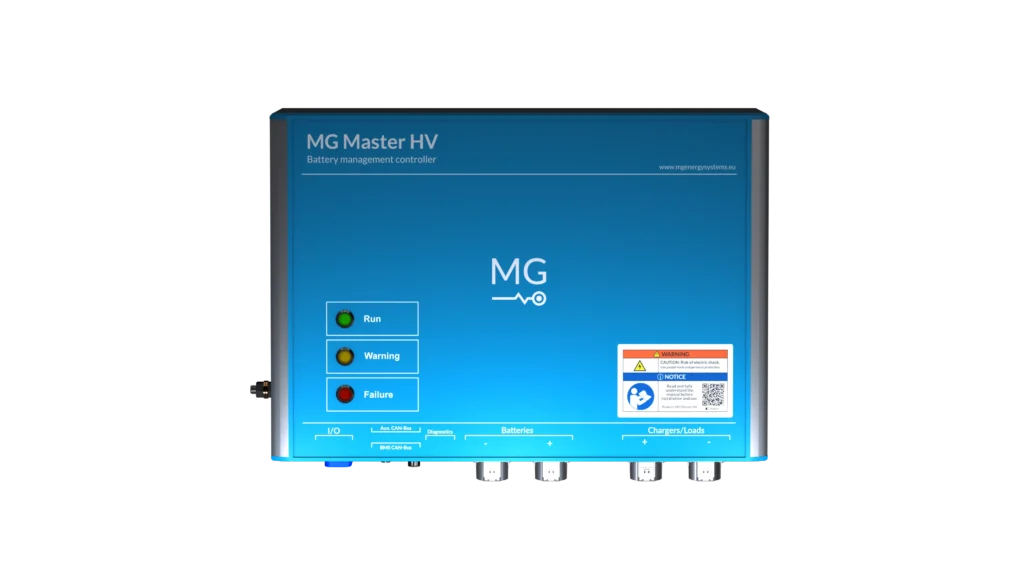


Battery Management System
Master LV
Master HV
Monitoring & Control
Energy Monitor
Connect App
Energy Portal
Battery Combiner
SmartLink MX
MG Batteries
4 of 4